 This lab is an example for a typical VSX Deployment scenario – one shared external Interface to Internet and separate Internal interfaces for each VSX virtual firewall.
 This lab also is second part of earlier post :
Creating Checkpoint VSX and Virtual System – Part 1
In that previous post, it already shows how to create a new VSX gateway through SmartConsole. This lab will show the steps how to create two VSX virtual firewalls and how to set up a virtual router. Two internal interfaces will be used to test the traffics from two different networks.
Table of Contents
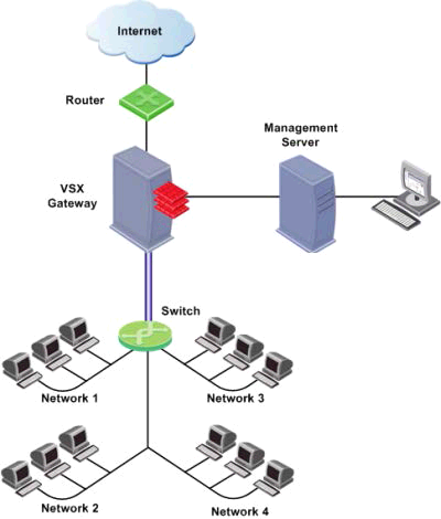
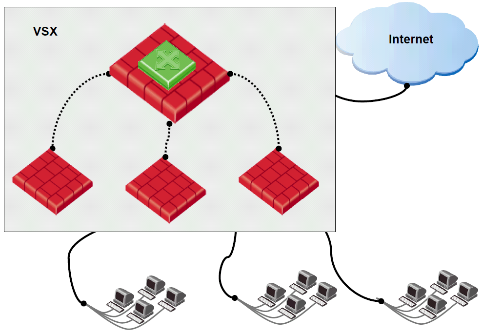
Topologies:
Basically, in this lab, there is one physical VSX gateway with two logical VSX virtual firewalls. Each virtual VSX virtual firewall has two interfaces , External and Internal.
Steps:
1. Follow the previous post “Creating Checkpoint VSX and Virtual System – Part 1” to add a new VSX gateway into Smart Dashboard.
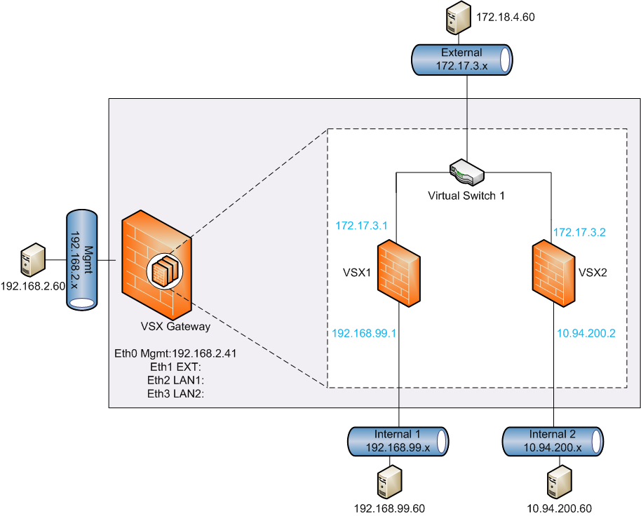
The new VSX Gateway has four physical interfaces as shown in the following:
- Eth0 Mgmt:192.168.2.41
- Eth1 EXT: for 172.17.3.x External Network
- Eth2 LAN1: for 192.168.99.x – VSX1 Internal Network
- Eth3 LAN2: for 10.9.200.x – VSX2 Internal Network
After new VSX Gateway (CP-VSX) added into Smart Dashboard, the webUI in browser will show:
Web UI is not supported in VSX mode. Please use Clish for OS configuration.
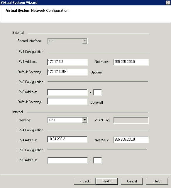
2.Adding vsx1 and vsx2 into CP-VSX


3. Check Network Topologies on both vsx1 and vsx2

